
There is a lot of good second hand 11mm factory turbo compensated injector pumps available to pickup on marketplace and gumtree.
These pumps were available on 2003+ Gu factory turbo Patrols and utilised an electronic timing control system to help the engine meet the emission standards of the day.
For this reason owners of early GQ Patrols often pass up on these looking for the hard-to-find Non TCV factory compensated pumps fitted to the 1997-2003 GU Patrols.
Both of these pumps are capable of producing almost exactly the same amount of power and torque which will depend on their age and condition above all else.
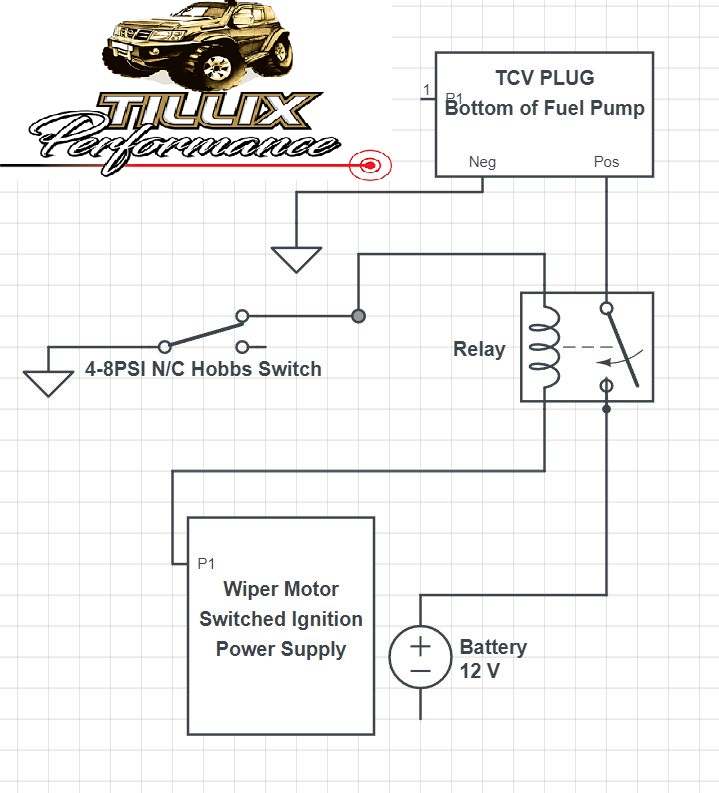
In order to install a TCV pump on a GQ patrol, you need just a basic power supply system for the TCV solenoid and a boost activated switch.
Why people avoid TCV Pumps when turbocharging their GQ Patrol
In the GU Patrol, the timing control system is operated by an ECU mounted in the cab that is fed signals from the Crank angle sensor, a Throttle position sensor mounted on the fuel pump and a needle lift sensor inside the number one injector.
With that system in place the ECU is able to determine what it should be doing with the timing based on engine speed, load and if the factory EGR system is operating or not.
The good news is that none of those sensors will be used in this basic control system so I wont go into any more detail about how and why the system was designed like that.
In the most basic explanation of why it matters that we use this system, the pump provides far to much timing at idle and very low rpm causing a very rattly idle and excessive black smoke under acceleration.
If we leave the system disconnected this is the downside to using these pumps.
Once the system is powered on, the solenoid in the pump will take the timing back to a base value suitable for low rpm operation and idle.
This system is not a perfect solution to the problem, but the most cost-effective and it works just fine on 99% of applications where someone is wanting to turbo their GQ and get far better tune-ability and more power than a non-compensated pump can provide.
As the factory ECU is not used in this situation, you can play around with the static timing of the injector pump to get the best result. This is best done on a dyno so you can measure the changes in torque as you adjust the static timing.
Somewhere around 0.65-0.7mm is going to be ideal if setting it via dial gauge during installation.
If you have an adjustable hobb switch you can play around with the activation point of the TCV solenoid to extract as much torque as possible while keeping soot down at low rpm.
Around 1700-1800rpm is the point that most engines want the system to be at full advance.
Its important to note, the overall dynamic timing of the injector pump is still governed mechanically inside the pump throughout the RPM range. Once the TCV Solenoid is unpowered, it will just allow the mechanical components of the injector pump to reach their maximum potential timing position.
One of these pumps in excellent condition with supporting mods and a lift pump can supply enough fuel to make roughly 130-135KW and 400-450NM of torque at the wheels.
More Information
Refer to our mechanical engine tuning guide here for a basic rundown on how compensated and non compensated pumps differ and how to tune them.

Hi there I am enquiring about the diagram for tvc does the hobbs switch need to be fitted to intake in order to activate or is this just power for tvc cheers.
The hobbs switch is to activate the TCV once the engine reaches a certain boost pressure. It just prevents the engine from sitting there at idle rattling from over timing. And helps spool the turbo a little quicker by having the timing retarded low in the rev range.
Hi Lindsey excellent thank you for that and one more question do I fit the hobbs switch just anywhere on inlet
Anywhere you can get a closed boost source from is fine mate. Ie, tpiece on a boost gauge line, into the intake manifold or pipework all ok.
Just not on the same line as a wastegate or boost controller.
Hi Lindsay, I’m confused at to what this system does in normal operation. Given your operation description shouldn’t the hobb switch have power connected to pump at idle and below boost then disconnect from the pump (advance) under boost acceleration ?? I have one thus trying to sort out the set up for it. If it rattles when pump is un-powered than it’s too advanced and the solenoid when powered retards it to standard base position????
Hi Andrew.
Yes that is exactly how it works mate. The NC means normally closed with the Hobbs switch. So in the diagram, the hobbs switch will be closed below 4-8psi (where ever you set it to) Which will in turn allow the relay to pass voltage to the TCV. So at low boost/idle the circuit will be powered, thus reducing the timing.
When the hobbs switch goes open circuit above your set boost point. The earth to the relay is broken and stops power getting to the TCV.
Hope this clears it up for you
So the other brown wire, far left is 12v for fuel shutoff sol?
None of the wires in this diagram show the fuel shut off solenoid.
It is located directly under the back of the compensator, under the fuel screw.
What wires do you use for the fuel shut off solinoid. Td42ti pump has 3 wires gq has 2.
If it has the NATS module on the pump you will have to remove it and run an eyelet directly onto the fuel shut off solenoid.
Only one wire is required to run the pumps on GQ or GU.